

SSD Structures and Best Practice
In recent years, Solid State Drives (SSDs) have seen a meteoric rise in popularity. SSDs have many advantages over Hard Disk Drives (HDDs), which have been the most popular primary storage device for some time, however, the high cost of SSDs made them impractical for a home market, and thus widespread popularity. In recent years, the cost of SSDs has reduced massively in price, while the amount of storage they contain has increased. People of all professions and technical abilities now have access to the high I/O speeds and ruggedness of this storage device. However, this has raised the number of questions relating to SSD operation and reliability.
How do they work?
To understand the best practices for using an SSD, it is first important to understand how they work internally. The basic structure of an SSD is made up of NAND flash memory cells and a controller. The host computer is connected to the controller via a ‘host interface’ (NVMe, SATA, SAS), this controller is responsible for controlling the communication between the host computer and the NAND flash cells, being responsible for the reliable storage and retrieval of the data, as well as the firmware that manages garbage collection and error correction on the drive.
The NAND cells consist of Floating Gate Transistors (FGTs). The FGT is similar to a MOS transistor, with the addition of the Floating Gate between the Control Gate and the channel. The various gates in the NAND cell are separated with dielectric oxide which acts as an insulator, trapping electrons in the Floating Gate. The trapping of these electrons even when the charge is removed makes the flash memory non-volatile. Using a principle called Fowler-Nordheim Tunnelling, it is possible to pass electrons through a barrier when a high enough electric field is present. Using this principle, the potential charges surrounding a cell can be manipulated, allowing the electrons to tunnel into the Floating Gate, where it is trapped by the dielectric even when the SSD is not powered. By doing this process in reverse, the electrons can be discharged from the cell. The bit value of the NAND cell depends on this threshold voltage of the Floating. If the gate is charged, then the bit value is set to 0 and the cell is “programmed”. If the gate is not charged, then the bit value is set to 1 and the cell is “erased”.
Bit values of a cell and the four Cs
We know that the bit value of a cell is determined by whether the cell is charged or not. So far, we have discussed how one bit is stored using one NAND cell, this is called a Single-Level Cell (SLC). However, it is also possible to store more than one bit using the NAND flash cells. By measuring the threshold voltage of the Floating Gate for four different voltage levels of, you can define the values 00, 01, 10, 11. When the NAND cell defines the value of two (or more)bits it is a Multi-Level Cell (MLC). This allows the same amount of data to be stored as an SLC using half as many NAND cells. The diagram below shows how the threshold voltage of a cell can be manipulated and measured to increase the number of bits that are stored.
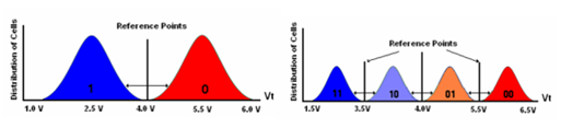
This does not stop with MLCs. By adding more reference points to the threshold voltage, you can further increase how many bits the cell can stored. Currently your NAND cell can be SLC (1 bit per cell), MLC (2 or more bits per cell), TLC (3 bits per cell) or QLC (4 bits per cell). The more bits per cell, generally, the lower price per GB of storage. However, this will also lead to lower Write/Erase speeds and a shorter lifespan.
Issues of SSD Longevity
It is common knowledge that after too many write and erase operations, the NAND cells will ‘wear out’, but what does this actually mean?
With enough read and write operations (charges and discharges of the Floating Gate), the dielectric oxide that separates the Floating Gate and the Channel becomes weakened, meaning that the electrons will no longer be trapped in the Floating Gateway, and the NAND cell can no longer be written to, this is known as ‘stress induced leakage’. By avoiding unnecessary write and erase operations to the SSD, we can extend the life of the NAND cells.
Another way the dielectric oxide layer is weakened is through ‘charge trapping’. When the charge is tunnelled into the Floating Gate, electrons can become trapped in the dielectric oxide. If a large enough number of charges become trapped in the dielectric oxide, then it will no longer be possible to reliably read back from this cell. Every stress event and write/erase operation that is performed on the NAND cell increases the chance of charge trapping occurring. Several studies have shown that, under the right conditions, it is possible to ‘detrap’ some these charges from the dielectric oxide layer. Studies have suggested that allowing inactive periods for the SSD where the external temperature is higher, will lead to more effective ‘detrapping’. This suggests that turning off the system to allow periods of inactivity for the SSD may have a beneficial effect on its lifespan, especially when stored in lower temperatures.
These two ways of ‘wearing out’ a NAND cell are further compounded by Write Amplification. This is an undesirable phenomenon that leads to a larger number of physical writes taking place to the disk, than logical writes from the host. The NAND cells are grouped into pages, these pages are then grouped into blocks. NAND memory cells can only be directly written to when they are empty. If the NAND cell contains data, it must be erased before the new data can be written to it. Due to limitations of SSDs, the erase command will always affect an entire block and not a single page, as a result, when one page of the block is edited, the whole block must be erased. This results in a process called the read-erase-modify-write cycle. The contents of the block will be stored in the cache, the block is then erased, the edited page is then written to the block that is stored in the cache, and then the edited block that is stored in the cache can be written back to the empty block. This process leads to the increased number of physical writes increasing the chances of cells wearing out due to ‘stress induced leakage’ and ‘charge trapping’.
Lifespan of an SSD and how to extend it
One important question this raises is: what is the expected lifespan of my SSD? The lifespan of your SSD will first depend on the type of cell that it is using. As a rough guide, we can expect a SLC lifespan to be around 90,000 to 100,000 read/write cycles. This lifespan will decrease with the more bits that are being stored in the cell, we can expect a MLC’s lifespan to be around 10,000 read/write cycles and a TLC’s lifespan to be around 5000 read/write cycles. These values may sound low at first, however, these are for the blocks and not the device itself. The life of your device will be further extended by SSD features like wear levelling and over-provisioning, as well as write caching from the OS.
Wear levelling refers to the SSD controller/firmware’s ability to evenly distribute write operations across blocks on the SSD, to ensure that a disproportionate amount of wear does not occur to certain blocks, leading these blocks ‘wearing out’ faster. The two methods of wear levelling are dynamic wear levelling and static wear levelling. Dynamic wear levelling occurs when data is written directly to blocks that have a lower wear count than other cells on the drive. This is done by taking all the blocks in an erased state and comparing the erase count for each block. The block with the lowest erase count is written to first, then the block with the second lowest erase count, etc. Static wear levelling is similar to dynamic wear levelling, with the addition of static data blocks that are not being modified, also being moved from cells with a low erase count. This allows these blocks to be written to by other data. Wear levelling is more effective when an amount of unused space is maintained on the drive, as there is a pool of unused blocks that can have their erase count compared, and then be written to.
Over-provisioning allocates space on the device to controller operations, this space cannot be accessed by the user. This space is used by the controller to manage traffic and SSD operations (e.g. TRIM and wear levelling). By ensuring that there is a permanent space that can be used to perform bad block management, garbage collection, and wear levelling, space does not need to be found and used ‘on the fly’ to perform these tasks. This results in increased performance and lifespan of the drive. When blocks on the SSD wear out, they are replaced by blocks from the over-provisioned pool. A certain percent of the drive’s storage will have been assigned as over-provisioning from the factory; more can be manually assigned to increase these benefits.
The S.M.A.R.T tools that are included as part of the SSD’s firmware contain statistics and management tools for the SSD. These statics help you monitor the expected lifespan of your drive, including the number of spare blocks in the over-provisioned pool, temperature of the drive, and the erase count of the blocks. These tools will vary depending on the manufacturer of your drive. Due to the wear levelling algorithms, when the blocks on your drive begin to fail, they will do so at roughly the same time. SSDs are designed to fail on the next erase/program and not mid erase operation, to reduce potential data loss. When the drive runs out of spare cells, it will become read-only, and further write operations will be prevented.
To extend the life of your device as long as possible, we advise:
- Use an SLC SSD to reduce the number of writes that take place to each cell, they will have a higher number of read/write cycles.
- Assign a higher amount of the drive’s storage to over-provisioning, this will mean there are more blocks to replace the worn out blocks.
- Manage the temperature of your drive, data retention will be significantly reduced the hotter the device gets. The SSD controller will then correct this by rewriting the bit, increasing stress on the oxide layer of the rewritten cells.
- Have periods of inactivity for your drive at low temperatures, this has been shown to ‘detrap’ trapped charges from the oxide layer, potentially making cells that are experiencing charge trapping readable again.
- Leave free space on the drive to assist with wear levelling.
- Avoid unnecessary write operations to the SSD (e.g. Defragmenting the SSD).
You can download a 30-Day Trial of Macrium Reflect Home, Workstation, Server, Server Plus, or Site Manager.
Why are backups important for gamers?
Windows 7 deprecation and Macrium Reflect

