
How do HDDs work?

Introduction and History
The first hard disk, the IBM 350, was introduced in September, 1956 as part of the RAMAC (Random Access Memory Accounting) system. Although the IBM 350 may not look like the hard disk drives (HDDs) we know and still love today, it was the start of the storage media that dominated the computer storage sector. This domination went largely unchallenged until the introduction of commercial flash-based SSDs in the 1990s by SanDisk. Despite HDDs slowly being replaced by SSDs in many consumer and professional settings, they still offer the cheapest price per GB of storage, as a result they are often found where large amounts of storage (several TB) is required, and speed is not paramount. So this raises the question, how do hard disk drives work?
Physical Structure
Hard Disk Drives are made up of several physical components. The main components are: the platter(s), the spindle, the actuator, the actuator arm, the read/write head(s).
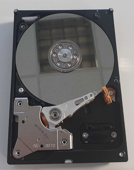
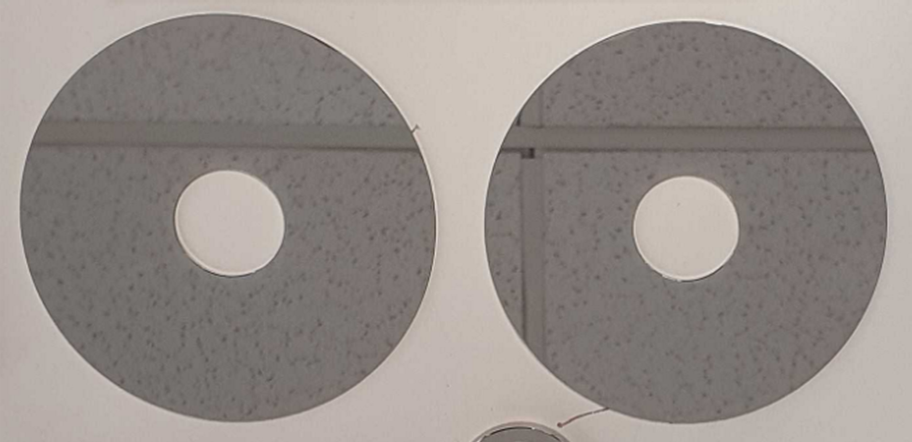
The Platter(s) - The hard disk platter is what physically contains the data in a HDD and is where a HDD gets its name. In contrast to soft (floppy) disks found inside a floppy disk, the platter in a HDD is rigid, usually made of glass, ceramic or aluminum. These disks are then coated with a thin magnetic layer. This magnetic layer is divided into billions of individual sections, each representing a bit. These sections can then be magnetized to create their own persistent magnetic field, data can be encoded in the states of the magnetic field. We now have the basis for how data can be stored on a platter. Each platter has two sides that can both store data, and each hard disk usually contains between one and five platters.
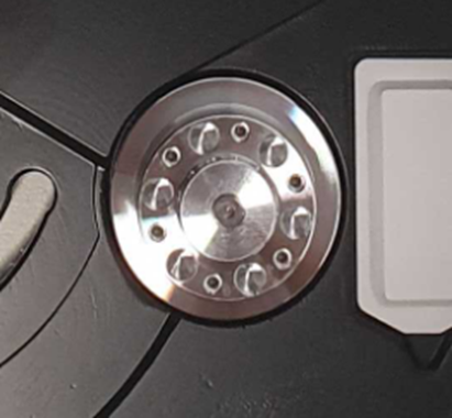
Spindle and Drive Spindle Motor - The spindle is responsible for holding the platter(s) in place. The spindle is attached to the drive spindle motor, which is responsible for making the platters spin, this is measured in RPM and for commercial uses usually varies between 5,400 and 7,200. It is important that the drive spindle motor rotates the disk at a fixed speed and with very little vibration. The spindle motor is connected to feedback circuits that can monitor the speed of the platter, the spindle motor’s speed can be controlled to mitigate any changes in the platter speed.
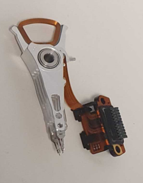
Disk read/write head - The disk read/write head is used to turn electric current into a magnetic field to manipulate the magnetic field of the platter (writing), or to turn the magnetic field of the platter into an electric current in the read/write head (reading). These read/write heads have an extremely low clearance over the platter, often riding on a thin layer of air, which acts as a lubricant and buffer between the read/write head and the platter. This is known as air bearing. The distance between the platter and the read/write head is known as the flying height. Each platter generally has two read/write heads, one for each side of the platter.
Actuator and Actuator Arm - The disk read/write head is attached to a triangular, lightweight alloy called the actuator arm. This arm is moved across the surface of the platter allowing the read/write head to access different tracks (more on tracks later) by the actuator. By combining the movement of the actuator and the spinning of the platter, the read/write head is able to move across the whole surface of the platter.
How is data on the HDD organized?
There are two key terms to understand how data is stored on a HDD: tracks and sectors. The platter in a hard disk is split into concentric rings, numbering into the thousands. These tracks can then be broken down further into sectors. A sector is the smallest addressable storage unit on a disk. Now that we know how data is stored on the HDD physically, how do we keep track of where all the sectors and tracks are? This is where addressing comes in.
Cylinder-head-sector (CHS) was an early method for addressing sectors on a HDD. To understand CHS, we have to understand each component separately. Cylinder defines tracks in the stack of platters that have the same track number. For example, a HDD with cylinders from zero (at the edge of the platter) to ten (at the center of the platter), the real amount of cylinders of a drive is much much larger than this, cylinder zero would contain all the outermost track on each platter. This essentially defines all the tracks that can be accessed without the actuator arm having to move. Head specifies which platter, and which side of the platter we are accessing. We can think of this as meaning “which read/write head are we referring to”. By combining the cylinder value and head value, we can specify a certain track on a particular side of a platter. The final part of CHS is the sector, this simply defines which sector on the track. By combining all three parts of CHS, we can address any sector on a hard disk using three numbers, the smallest being 0/0/1 (in CHS addressing there is no sector 0, and sector numbers start at 1).
The second addressing scheme is Logical Block Addressing (LBA). LBA is considerably simpler than CHS, and numbers each sector starting at 0, for example LBA0, LBA1, etc. The physical location of each sector is largely irrelevant and is translated by the disk’s firmware. This gives the disk firmware the freedom to map data dynamically, thus bad sectors can be replaced with sectors from a pool of ‘spares’ without exposing disk specifics to the operating system. The host can access particular sectors on the HDD using the LBA number, this abstracts a lot of the physical storage considerations from the host and makes addressing independent of disk structure. This allows disks to be cloned to a replacement of a different type without complex remapping. LBA has replaced the CHS as the primary method for storage addressing.
Writing Data (Magnetic Recording)
We now know how data is physically stored on a hard disk and how it is organized but how is the data written?
Conventional HDDs make use of a recording technique called perpendicular magnetic recording (PMR). You may also hear PMR called conventional magnetic recording (CMR). PMR is an improvement over an earlier form of magnetic recording called longitudinal magnetic recording (LMR). PMR contains a soft magnetic underlayer beneath the recording material, this underlayer conducts magnetic flux (a measurement of magnetic field passing through a certain point) extremely well. This has the effect of creating an extremely strong magnetic field around the recording material, much higher than the magnetic field used in LMR. This has several advantages, with the use of stronger electric fields, materials with a higher magnetic coercivity can be used for the recording layer. These materials require stronger magnetic fields to magnetize, meaning that once the bit has been set, there is less chance of the bit being affected by extraneous magnetic fields.
However, a third, newer magnetic recording technique is becoming available: shingled magnetic recording (SMR). We can think of PMR recording tracks next to each with a small gap between each track, at no point do they overlap. SMR changes this by writing overlapping tracks. When looking at the data recorded on the platter, these tracks look similar to roof shingles, with each track overlapping onto the next. This makes each track narrower, allowing for more tracks to be stored on a platter, increasing the storage density. The overlapped tracks are then organized into zones, the shingling breaks at the end of each zone.
However, there are drawbacks to SMR. Since the tracks overlap, direct modification of a track is not possible as the track overlapping onto it must also be rewritten, as a result all the tracks in the zone must also be rewritten, increasing the amount of time the write takes, somewhat similar to write amplification found in an SSD. However, since the shingling breaks at the end of each zone, only one zone must be overwritten in its entirety and not the whole side of the platter. SMR drives also contain sections of LMR that can be used as a cache to store these writes, they can be then written to the SMR sections of the disk during periods of low activity.
As the demand for cost-effective mass storage continues to grow, we can expect to see SMR drives become more common. From a disk manufacturer’s point of view, SMR is perfect for increasing the storage density of their drives without adding more platters. However, not everyone is happy with this, as there are claims that SMR drives may suffer performance issues when compared to PMR drives. For a fascinating and in depth comparison between PMR and SMR drives, please see this article by ServeTheHome. This culminated in legal action against WesternDigital for allegedly ‘downgrading’ WD Red NAS hard drives from PMR to SMR without informing consumers:
“Hattis Law has filed a lawsuit against Western Digital Corporation alleging that Western Digital secretly switched many of its hard drives, including its WD Red NAS hard drives, to inferior shingled magnetic recording (SMR) technology, deceiving and harming consumers.”
- Hattis and Lukacs
You can read more about this controversy in our blog post here.
Interfaces
Due to the amount of time that we have used HDDs for, they have been available using several different interfaces.
Two of the earliest interfaces that were widely available were the ST-506 and ST-401 developed by Seagate 1980 and 1981. Although these two interfaces were similar, ST-401 included several improvements over ST-506, improving speed and increasing drive capacity. The SCSI and IDE/ATA standards were a big step in the development of disks, as they included an embedded controller in the disk itself. This enabled error correction, remapping, and performance optimization specific to the disk itself. SCSI was introduced in 1986 and Parallel ATA (PATA, also known as IDE) was first introduced around the same time, being developed by Western Digital and Compaq in 1986. Originally the standard was named the AT Attachment (ATA) due to it connecting directly to the 16bit ISA port which was introduced by the IBM PC/AT. PATA was succeeded by Serial ATA (SATA) which was first available in 2003, in the Seagate Barracuda SATA V, the first hard drive to make use of the SATA interface. Prior to SATA being announced in 2000, PATA was known as the AT Attachment or ATA. SATA rapidly became the dominant interface for storage devices, and is by far the most common interface used by hard disk drives today. The other interface that you may see today is Serial Attached SCSI (SAS), which uses the SCSI command set.
Limitations of HDDs and HDD lifespan
Due to the mechanical nature of HDDs, there are several drawbacks that must be considered. The two of which are ‘rotational delay’ and ‘seek time’. These two terms are closely related and both affect how long it takes for a sector on a platter to be physically accessed (both of these are measured in milliseconds, ms). Rotation delay is the amount of time between an I/O operation being created and the amount of time it takes for the platter to rotate from one sector to another. Imagine a disk with 64 sectors on a track, the rotation delay will be larger when moving from sector 1 to sector 32 than it would be from sector 1 to sector 2. Seek time relates to the movement of the read/write head from one track on the platter to the next, the further away the next track is from the current track, the higher the seek time will be. Although these brief periods of waiting in the HDD may seem inconsequential at first glance, this can seriously impact random I/O performance as the read/write head must move more.
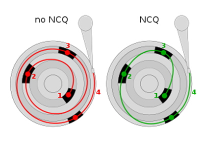
The next drawback for HDDs is the ability to only execute one command at a time, as a result it is extremely important that commands are serviced in a logical fashion to reduce the amount of seek time and rotational delay between each command. The SATA AHCI protocol contains the Native Command Queuing (NCQ) extension. This enables hard disk drives to internally optimize the order in which read and write commands are executed. AHCI has a single command queue that contains 32 commands. These commands can then be serviced by the HDD’s internal scheduling algorithm in the order they deem most appropriate. Some of the common scheduling methods for HDDs are: First Come First Serve, Shortest Seek Time First, Elevator (SCAN), Circular Scan (C-SCAN) and C-LOOK. The image below shows NCQ optimizing the order of 4 commands:
Although hard disk drives have been optimized to execute commands in efficient ways it is inferior when compared to flash storage, especially newer flash drives that use the NVMe protocol, which has 65535 queues with 65536 commands per queue. Coupled with SSD’s lack of moving parts, meaning no rotational delay or seek times, the performance of a HDD is unable to match that of an SSD.
The moving parts inside a HDD are also much more susceptible to shock and vibration damage than flash media. One example of shock damage is a head crash; this occurs when the read/write head makes contact with the platter underneath. This causes severe damage to the platter as the magnetic is scratched away, potentially leading to data loss in whole tracks.
Proper care of a hard disk drive is key to ensuring the drive’s longevity. AKCP, who make tools for networked temperature, environmental and power monitoring in data centers, suggest that turned off hard disk drives can be safely stored at between -40°C (-40°F) and 70°C (158°F). Although, they note that these temperatures will vary between manufacturers. Where possible, all storage media should be protected from extreme temperatures and shocks.
With this in mind, how long can you expect your HDD to last? This is a difficult question to answer. BackBlaze conducted a study of over 200,000 disk drives from a variety of manufacturers. They noted that they saw a failure rate below 2% for the first three and a half years; the failure rate rapidly increased up to year six. They concluded that a reasonable estimate of the median life expectancy of a hard drive to be about six years and nine months. For more information about the study and BackBlaze’s findings, we highly recommend reading their article here.
Macrium Reflect and Hard Disk Drives
Due to the cheaper price per GB of storage when compared to flash drives and long life span , HDDs can make the perfect storage media when high-speed random I/O is not required, e.g. storing backups.
Although, as we noted above, hard drives will eventually fail. It is important that multiple copies of backups are created. Whether this is syncing your backups to a second storage device or scheduling an extra set of backups to a second storage device, redundant copies of backups will protect you in the event of a backup destination drive failing. The 3-2-1 backup strategy ensures that in the worst case scenario, you will still have a backup to restore. For more help planning your backups, please see this blog post. It is also worth noting that hard disk drives should not be considered for archival storage, as leaving it unpowered for several years increases the risk of seized platter bearings and head mechanics when the disk is repowered.
For an in-depth breakdown of different storage media and advice on which storage media to choose, please see this blog post.
See also: How do SSDs work?